
Cameras have become ubiqutious. They have become the most common sensor in any robotic system that perceives the world. This is because cameras pack a lot of information in a single image. As the old adage goes one picture is worth a thousand words.
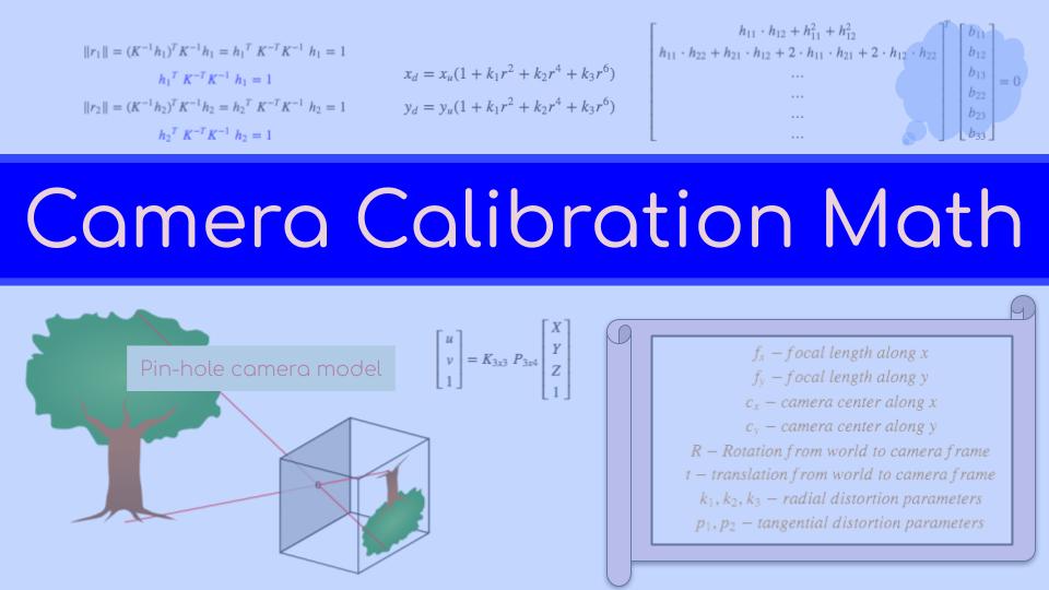
The pin-hole camera model is a simple mathematical model to study cameras. This model assumes that you are looking at the world through a small pin-hole. Most of you should be familiar to this and have read about it in your high-school physics text book. This model explains light passing through a tiny aperture (pin-hole) and projecting an inverted image on the other side. This does not involve the use of any lenses. However the pin-hole model can be generalized to most of modern camera systems which use lenses (to focus more light to the sensor).
In this article we will focus on understanding the camera projection equation $$ \begin{bmatrix} u \\ v \\ 1 \end{bmatrix} = K * [R | t] * \begin{bmatrix} X \\ Y \\ Z \\ 1 \end{bmatrix}$$ This equation explains the projection of a 3d point $\begin{bmatrix}X & Y & Z \end{bmatrix}^T$ in the world coordinates to a point $\begin{bmatrix}u & v\end{bmatrix}^T$ in the pixel coordinates. Here $K$ is the intrinsic/camera matrix which describes the specifics about the camera we are looking at. It encodes the focal length of the camera along with the camera centers in pixel coordinates. Let us see how we arrive at this equation.
Derivation
The figure below shows a simple pin-hole camera setup with an object observed through a pin-hole forming an inverted image.

Let us say the object is $Z$ meters from the pin-hole and $X$ meters high. For a screen distance of $f$ meters from the pin-hole, a $u$ meter inverted image is formed on the screen. Here $f$ is called the focal length. Using similar triangles we can say that $$ \frac{X}{Z} = \frac{x}{f} \implies x = \frac{X.f}{Z}$$
If we include the other dimension as well, we have, $$ \frac{Y}{Z} = \frac{y}{f} \implies y = \frac{Y.f}{Z}$$

These two equations can be represented in the matrix form as, $$\begin{bmatrix} x \\ y \\ 1 \end{bmatrix} = \begin{bmatrix} f & & \\ & f & \\ & & 1 \end{bmatrix} \begin{bmatrix} X \\ Y \\ Z \end{bmatrix}$$
As we can see from the image above, the principle point goes through the center of the image plane. However the pixel coordinates are counted from one of the corners for convinence. These are the u,v coordinates. So we subtract a constant offset from the projection point to get the values in pixel coordinates.
$$ u = x - c_x \\ v = y - c_y $$
Substituting $x$ and $y$ values and absorbing the negative sign into $c_x$ and $c_y$, we get,
$$ u = \frac{X.f}{Z} + c_x \\ v = \frac{Y.f}{Z} + c_y $$
Again in the matrix form,
$$ \begin{bmatrix}u \\ v \\ 1 \end{bmatrix} = \begin{bmatrix}f & 0 & c_x \\ 0 & f & c_y \\ 0 & 0 & 1 \end{bmatrix} \begin{bmatrix} X \\ Y \\ Z \end{bmatrix}$$
The $\begin{bmatrix}f & 0 & c_x \\ 0 & f & c_y \\ 0 & 0 & 1 \end{bmatrix}$ matrix is called the intrinsic matrix or camera matrix and often represented as $K$.
This is assuming that the camera center is at the origin of the world frame. This is a workable assumption if we are just dealing with a single camera. But if we have multiple cameras or if we have multiple sensors and want to set a different sensor as the origin of the world frame, or if the camera is moving, we will need a way to represent the camera in a different coordinate frame. To accomplish this we will introduce another matrix that will project the 3d point $Q$ from the world frame to the camera frame using a rotation $R$ and translation $t$.
$$ \begin{bmatrix}u \\ v \\ 1 \end{bmatrix} = \begin{bmatrix}f & 0 & c_x \\ 0 & f & c_y \\ 0 & 0 & 1 \end{bmatrix} \color{red}{\begin{bmatrix} R & | & t \end{bmatrix}} \begin{bmatrix} X \\ Y \\ Z \\ 1 \end{bmatrix}$$
Notice the 1 added to the fourth row of the 3d point. This is the homogeneous form. The multiplication of $[R | t]$ with $[X \; Y \; Z \; 1]^T$ is pretty similar to the coordinate transform except that $[R | t]$ is not a homogeneous transform (its missing the last row). This is to the make it compatible with the camera matrix, $K$ on the left which is a 3x3 matrix.
As I mentioned before $[R \; | \; t]$ transforms a point in the world frame to the camera frame $[R^c_w \; | \; t^c]$. So the camera center in the world frame is given by $C^w = -R^w_c t^c$. Notice the $R^w_c$ is the inverse of the $R$ in the projection equation.
$$ C^w = - R^T t$$
It is important to know this relationship because it comes up when you try to do projection from the camera (ray tracing) and when performing multicamera operations.

Use the share button below if you liked it.
It makes me smile, when I see it.